To achieve these science goals, we are building a new visible beam combiner for the CHARA array, called CHARA/SPICA. It is designed for the measurement of the angular diameters of 1000 stars and will provide a major step forward in terms of magnitude and precision with respect to the present situation.
The combination of the six CHARA telescopes equipped with AO with a low-resolution (R=150, Dl=3.5-7nm) spectrograph (50 channels over 650–950 nm) will yield 750 different spatial frequencies in one single observati750on and thus will allow precise determinations of angular diameters.
For a subsample of bright stars, a medium (R=4300, Dl=88nm) and high (R=13200, Dl=29nm) spectral resolution mode (500 channels) will allow spectral imaging of stellar surfaces and environments for higher accuracy on the stellar/planetary parameters and studies on the kinematics of environments and atmospheres.
To push the limiting magnitude in the different modes and give access to a large sample of stars, CHARA/SPICA is assisted by a fringe tracking system in the H band to reach “long” (200 ms– 10 s) exposures of the fringe signals in the visible. The design is based on the ![]() FRIEND prototype extended to 6T. A great advantage with a fibered instrument is that the injection module and the instrument itself are completely decoupled. This is not only interesting for implementation but also for the alignment where all the efforts could be focused on the injection system.
FRIEND prototype extended to 6T. A great advantage with a fibered instrument is that the injection module and the instrument itself are completely decoupled. This is not only interesting for implementation but also for the alignment where all the efforts could be focused on the injection system.
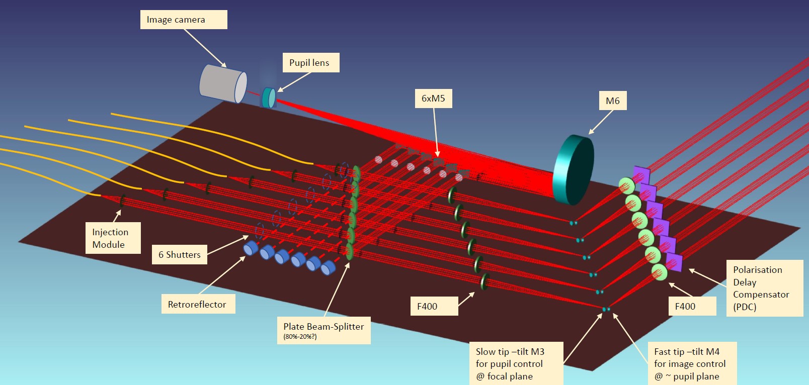
SPICA-VIS final optical design. from the CHARA beams (upper-right corner) to the optical fibres after the injection modules (left). The first F400 doublet allows to reimage the image plane on the M3 mirror and the pupil plane on the fast tip/tilt M4 mirror. The upper part of the design contains the control for the alignment and injection.
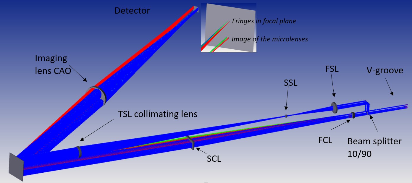
Design of the CHARA/SPICA spectrograph: from the V-groove with the fibres in the V-groove (right) up to the detector (middle-up) with the dispersed fringes and the dispersed photometric channels, selected by the 10/90 beam splitter. The fringes are dispersed in an image plane whereas, for the photometric channels, we disperse the image of the microlenses.